
Improving Relay Reliability for Telephone Exchanges
-- The Pursuit Excellence for Five Decades
Abstract: The highly reliable operation of dial-based telephone exchanges depended on robust relays with electrical contact integrity. Bell System engineers spent half a century innovating materials, mechanical designs, and protection networks, to overcome metal erosion, contamination, polymer formation, misalignments, noise, contact locking and more. This relentless pursuit of relay reliability, maintained by essential switchmen, was crucial for both call quality excellence and economic viability. Appendix B has remarks from many experienced switchmen on maintaining relay-based systems.
Introduction
The intricate symphony of a dial-based telephone exchange, once the backbone of global communication, hinged critically on the dependable performance of 300 million electromechanical relays (1956) [Ref 7]. These switches were the workhorse of the network. In North America, 35 million subscribers made 250 million telephone calls per day in 1950 [Ref 18]. During the golden age of dial telephony, roughly from 1900 until the mid-1970s, over a billion relays were manufactured by Western Electric Company and deployed across North America and worldwide by others such as Automatic Electric Company (North America start), Siemens & Halske (Germany), L.M. Ericsson (Sweden), ITT (International Telephone & Telegraph, USA/Europe) and others.
A Number 5 Crossbar dial exchange for 10K lines contains nearly 2,000,000 precious-metal contacts for establishing connections. Interestingly, 1,200 relays, with an average of seven contacts per relay, are involved in establishing a call from one local subscriber to another. When the operations per call are multiplied by the 50,000 average daily calls that may be handled by an office, and by 365 days/year, the total number of relay contact operations per year is over a hundred billion per exchange [3].
The sheer scale of operations means that possibly a single relay failure rate could translate into significant service disruptions. This was especially true when the relay was used in “common control” equipment (example, a crossbar Marker) that may be orchestrating thousands of calls per hour. This reality motivated the Bell System's engineers on a 50-year journey to advance relay contact integrity and structural reliability. A forty-year trouble free life was the goal set for Bell’s switching equipment according to [21]. Although this article focuses on reliability advances by Bell engineers, advances were made by other world class manufacturers with similar goals.
The Relay
The electromechanical relay was patented in 1838 by Edward Davy (1806-1885) in England. Initially it was used to repeat, or relay, telegraph signals. It was often simple, with a set of make or break contacts. Figure 1 shows a basic relay’s parts. Note the flexibility of the “swinging arm” (10) and the point contacts on 10, 11 and 12.

Fig 1, left side, relay at rest, 10 connects to 11. Right relay is engaged by current flowing through the coil’s terminals 2 and 3 causing 10 to connect to 12
Edward Craft of Western Electric invented the Flat Spring relay (images of Craft’s relays) in 1915. It was the first of many generations of relays designed for volume production for switchboards and dial exchanges. Each generation became more reliable as engineers learned what factors were important for creating longer lives for the relay's contacts and mechanical design.
This article traces that remarkable timeline, highlighting the key challenges identified, the scientific understanding gained, and the innovative engineering solutions implemented to extend the life and dependability of these vital components. Relay electrical contacts are the key focus here, but other factors are also covered to present a comprehensive review of electro-mechanical relay reliability. First, let’s look at a few examples of commonly used telephone relays starting from 1915.
See Fig 2 for an assortment of R type flat spring relays used to count dial pulses in a Panel exchange. Western Electric produced flat spring models A, E, F, H, R, and T [17] and these were extensively installed between 1915-1938.

Fig 2, Type R flat spring relays in Register circuit in a Panel exchange circa 1920's
(Image from Connections Museum of Seattle)
The 3000-type barrel relay, a product of the British General Post Office (GPO), was adopted as a standard in 1932 [19]. It was developed by GPO engineers and manufactured by partners such as the Automatic Electric Company.
It was a modular and versatile relay used in both Strowger and Crossbar systems. The 3000, and its younger brother the 600, were the backbone of British telephone switching for decades. See Fig 3.

Fig 3, Type 3000 with dome contacts
Western Electric manufactured Step-by-Step Strowger switches too, and they extensively utilized the five barrel-relay types 221-225 [17]. This relay was relatively similar in look to Fig 3.
To appreciate the importance of the generic switch (relay or other), see this explainer video on the Essential Switch.
The Early Days: Confronting the Mystery of Contact Erosion
From the very inception of telephone switching, engineers recognized that contact operation inherently involved the generation of high voltage transients across a contact when opening a circuit with an inductive load, such as another relay. The contact “sparking” may lead to eventual contact failure and not close or open as expected. The control of this contact erosion became a problem of major importance [13], [14].
The physical manifestation of contact degradation is usually a material transfer between coupled contacts. Fig 4 shows such a case (no arc protection devices used). Imagine the contact degradation after millions of arcs.

Fig 4, an image of a typical anode pit (left) and cathode accumulation (right) due to a single arc. Magnification is 2000X [10].
When a molten bridge is broken by separation of current flowing contacts, the highest temperature reached before rupture is below the boiling point of the metal. For Gold the “rupture temperature” is at 2,232 C (2,064 C melting point, 2,970 C boiling point). Incredibly, an opening contact carrying 1 amp may have a current density at the (very small) arc location of 10 billion amps per square centimeter [12]. Figure 5 shows the effect of many arcs on the integrity of the contacts. Regarding erosion, the anode contact loses material due to metal vaporization and the cathode contact receives the deposited metal.

Fig 5, point and disc showing point erosion and transfer of metal to disc using No. 3 contact metal [11].
This microscopic world was mostly hidden from the craftspersons maintaining the equipment. As they walked through the equipment aisles during busy hours, small volcanoes were erupting on hundreds of relays with contact area temperatures reaching ~2,200 C degrees. This was before contact protection was common. On occasion they needed to burnish (using a specialized small metal file) the contacts to clean a fault. Fig 6 shows two extreme examples of contact erosion and metal build-up. See the short narrative “Sherlocking a Marker Failure” (Appendix in the link) for more insights into relay maintenance by service personnel.

Fig 6, an example of contact erosion of a palladium contact (left) and contact build-up on a silver contact (right). No contact protection networks are used. From [3]
A New Era of Observation: Unveiling the Transients (1940s)
A significant leap forward in understanding contact behavior came with the rapid advancements in cathode ray oscillographs in the late 1930s and early 1940s. This enabled the visual observation of transient voltages. Single pulses lasting a fraction of a microsecond and complex transients with components as high as 5 megacycles could be clearly resolved and photographed.
With these improved techniques, the complex dynamics of contact operation could be thoroughly investigated. For instance, upon contact closure in a typical circuit, the initial event was the charge or discharge of the connecting wire (up to hundreds of feet) through the contacts. This resulted in an oscillation with a peak current of about 0.5 ampere, concluding before the steady current began to build up. If additional branching wires were attached, the current surge increased, leading to potential "explosion" and destruction of the contact metal.
Contact opening proved even more complex, influenced by factors such as current flow, load inductance, humidity, dirt, surface films, absorbed gases, contact separation speed, surface roughness, wiping motion, and material properties. When steady currents exceeded certain values (0.4 to 1 ampere), a metallic arc formed as contacts separated, lasting several milliseconds before breaking into a complex transient. A detailed understanding of transient phenomena provided the foundation for designing contacts and circuits to mitigate erosion and maintain reliability [12]. See Appendix A for insights on the complexity of contact transients.
Engineering for Enduring Performance: Evolution of Reliability Factors
The goal was to design contacts for dependability, long life, and low cost, often requiring trade-offs based on the contact's function. Starting from about 1915, a relay’s flexible arms (see Fig 1) used non-magnetic springs consisting of punched and formed parts made from non-ferrous brass, nickel-silver, or phosphor bronze (used for guitar strings too). The smaller electrical contact area at the tip was often a different material, sometimes very expensive. The following sections cover six key factors that influence relay reliability. The first four focus on the importance of contact integrity.
The primary reliability driver is the choice of metal at the electrical contact region [3]. Let’s consider this first.
1. Contact Materials: From Platinum to Palladium and Gold Alloys
Telephone switching contacts were broadly classified into noble or precious-metal contacts, and base-metal contacts. Precious metals were favored because they did not readily oxidize or tarnish, thus maintaining low resistance. Base metals, such as copper or nickel, would oxidize and develop high resistance, making them unsuitable for reliable contact operation. The precious metals included gold, silver, and the six so-called platinum metals (platinum, palladium, iridium, ruthenium, osmium, and rhodium).
Early precious metal contacts were primarily platinum. However, market prices and availability drove shifts to new materials. In the Bell System, four main contact metals were developed, all numbered for identity [11].
No. 1 metal: A gold-silver-platinum alloy (69% gold, 25% silver, 6% platinum by weight) introduced between 1915 and 1920.
No. 2 metal: Palladium was introduced around 1925, gradually replaced platinum, and by 1932, replaced No. 1 metal contacts in many applications.
No. 3 metal: An alloy of 70% gold and 30% silver. See Figure 5.
No. 4 metal: An alloy of palladium and copper (60% palladium, 40% silver)
Each of these choices were used by Western Electric for relay production over the years.
Pure silver contacts were used in the Number 1 Crossbar system circa1937 [3]. While silver tarnished and developed limited contact resistance, it was acceptable for relay-switching circuits where the arc could break down films but caused objectionable noise in talking circuits. Palladium contacts, used in the crossbar switches, were for talking or tone circuits or where low-contact resistance was required. Surprisingly, even a 1 ohm contact resistance can introduce objectionable “microphonic” audible noise when contacts rub together due to the vibrations of many crossbar switches in the same frame.
The building up and pitting leaves both contacts roughened. If the opening and closing motion were along a perpendicular to the face of the contacts, this roughening would ordinarily have little effect. But with a slight sliding or rocking motion at the contacts after they come into engagement, small projections on one contact may lock mechanically in a cavity on the other and thus prevent the contacts from opening when they should. When contacts have been locked, measurements have shown that forces more than 100 grams may be required to separate them [4]. If the lock was detected, a craftsperson may need to burnish the contacts to prevent relocking.
2. Contact Protection: Taming the Arcs with "Spark Killers"
Understanding the destructive nature of transient arcing led to the development and widespread adoption of "spark killers". These typically consisted of a capacitor and resistance in series, shunted across the contact or load. Their primary function was to keep the voltage below the sparkover point until contacts had separated a safe distance, thereby significantly reducing erosion. The working voltage of a telephone plant is a low ~48 VDC, so from where do the sparks arise?
When a contact opens, the rapid decrease of current in the inductive load creates a sudden negative voltage jump (so called Back EMF) which can arc across the small gap at the barely opened contact. See Fig 7 showing a >300 V transient. Also, any stored energy in the capacitance and inductance of the connecting wiring (very short to 100+ feet) may cause a discharge across this conducting gap, resulting in a current surge. This process can repeat rapidly causing eruption and metal transfer.
Back EMF is the voltage generated by a relay coil when the current changes (or stops completely). The current alters the magnetic field, and according to Lenz’s Law, the coil generates a voltage that opposes the change. The bigger the decrease in current, the bigger the back EMF, in principle.

Fig 7, This shows the negative voltage between two opening silver (relay) contacts in which the steady current (0.25 ampere) driving an inductive load is sufficient to cause a brief metallic arc [2].
Contact protection networks (CPN) like the Western Electric 186A-type (0.3 µf capacitor in series with 120 ohm resistor) and the smaller 185A-type (0.1 µf capacitor and 470 ohm resistor) were developed in the 1940’s to reduce, or snub, the voltage peaks. The peaks for unprotected contacts could reach 2,000 volts, while protected circuits had no arcing damage. Fig 8 shows how a CPN is used (contact of interest, upper left). The CPN may be directly across a contact or across the relay coil. In either case, the network reduces the transient voltage such that the contacts do not arc or minimally so. Semiconductor diodes replaced CPNs for arc suppression in the late 1950s to early 1960s, shortly after they became commercially viable.
Contact protection became extensively used in systems like the Number 5 crossbar, significantly reducing contact locking [3], [8]. In British designed (GPO) telephone systems, the CPN is called a “quenching device.” This network was nearly identical to the Bell 185 type. A non-linear resistor made of silicon-carbide [22] was also used to quench.

Fig 8, Contact protection for an inductive load [15]
With many millions of CPNs across thousands of exchanges it was inevitable that some would silently fail (open) overtime. Of course, failures caused contact erosion and eventual circuit breakdowns. Long live the craftsperson.
As an aside, life-testing of relays was carried on in a specialized AT&T lab. Thousands of relays of various kinds with several different types of contact metals and varieties of contact protection networks were operated for several years. If a contact failed, its circuit would immediately indicate trouble to the test engineers [21].
3. The "Polymer Problem" and the Gold Overlay Solution (1950s)
A particularly vexing issue that emerged, especially with the use of palladium contacts, was the formation of a problematic organic deposit. An amorphous brownish material was found on non-arcing palladium contacts when operated in the presence of low concentrations of organic vapors. This polymer was a significant cause of "open" contacts, as it had insulating properties.
The sources of these organic vapors were a great mystery. It was finally identified as insulating materials such as cellulose acetate-filled coils and phenol fiber components, which gave off vapors, especially when heated during relay operation.
Encasing relays in sealed containers to exclude dust (good) was found to increase contact erosion and polymer formation due to the concentration of organic vapors (bad). The polymer could accumulate as compacted clumps or dust around the contact area. After hundreds of thousands of operations, these accumulations could cause contact failure by dusting off and falling into the contacting area [5].
In 50-volt telephone circuits, a failed contact would typically clear itself in about five operations, but this "low persistency" still meant transient failures. Furthermore, contacts carrying talking currents could become microphonic or noisy if contaminated with polymer deposits, especially when vibrated by nearby relay or crossbar operations. See Fig 9.
The critical solution to the polymer problem, particularly for non-eroding contacts like those in talking paths, was the development of a gold overlay for palladium contacts. The wire-spring relay (1952), while more reliable than the U relay in many aspects, initially showed a higher failure rate from polymer contamination, leading to this crucial solution.

Figure 9 – Replica (in testing apparatus) of a palladium contact with all inorganic relay components, showing organic deposits from purposefully introduced hexane vapors (organic) after 10^6 closures. Magnified 75 times [5].
For contacts not subject to erosion, like those in talking paths (no large voltage spikes) where polymer could cause microphonic noise, the gold overlay was crucial.
4. Contact Mechanical Design and Actuation
Beyond electrical characteristics, the mechanical design of relays profoundly impacted reliability. Let’s look at two factors.
Contact Locking: A common failure mode was "contact locking," where a closed contact would mechanically snag and fail to open due to roughened surfaces caused by metal transfer during arcing. This was partially addressed by improved spring actuation methods. The older "stud actuated" contacts allowed a slight sliding or rocking motion, making them prone to locking. The newer "card actuated" arrangement, introduced with the wire-spring relay, caused the moving contact to engage the fixed contact without sliding or rocking, greatly reducing the tendency to lock.
Open Contacts from Dirt and Twin Contacts: "Open" contacts, caused by small insulating particles (dust, fibers) trapped between contact surfaces, led to high resistance or open circuits. To combat this, several measures were employed: filtering air, enclosing equipment, and using contact covers. The most widespread method in the telephone plant was the adoption of "twin contacts".
The concept of twin contacts was simple: if one contact failed, the other, in parallel, would likely ensure connection. The theoretical improvement, if contacts were independent and dirt random, followed a "square law" (e.g., 1 in 1,000 failures for a single contact would become 1 in 1,000,000 for twins).
Figure 10 shows the twin contact configuration on a typical U relay introduced in 1938. Compare to the R-type relay’s (predecessor) single contacts in Figure 2.

Fig 10, twin contacts on U relay, from the author’s collection
In practice, this full improvement was not always achieved due to reduced force per twin contact and lack of complete mechanical independence, where dirt on one twin could affect the other. However, twin contacts still provided a significant improvement. Figure 11 clearly shows the improvement due to dual contacts. The GPO’s standard 3000 relay had twin “dome contacts” starting from 1932 [19].

Figure 11 – Comparison of failures of twin (U relay type) and single contacts (R relay type) [8]
The wire-spring relay (discussed below) achieved complete independence of twin contacts by mounting them on two separate wires rather than a single notched spring (as in older U and UB relays), further reducing open contacts from dirt. See Fig 12.

Fig 12, Independent action of twin contacts is limited on U and UB relays because both contacts are mounted on a single spring which is notched. The AF wire spring relay achieves complete independence by mounting the contacts on separate wires [16].
5. Coil Construction and Overall Relay Stability
The reliability of a relay also depended on its coil and structural stability. The three main points below are derived from [4].
Coil Corrosion: A prevalent cause of coil failure was "corrosion" of the fine wire, which was an electrolytic action within the coil in the presence of moisture and active impurities in insulating materials. This was particularly problematic for coils using small diameter wires. While vacuum impregnation could extend the life of coils with inferior materials, it did not eliminate corrosion as effectively as cellulose acetate (organic) and carried the risk of contaminating other vital relay surfaces as discussed earlier.
Pile-up Stability: The contact spring pile-up, comprising multiple springs, needed to maintain its position despite temperature, humidity changes, and mechanical shocks. This was ensured by using insulators with low moisture absorption, like phenol fiber, and high tensile strength steel for pile-up screws and clamping plates. During manufacturing, pile-ups were pressure-clamped while screws were tightened, improving stability through humidity cycles and preventing displacement during installation.
Magnetic Stability: Magnetic materials in relays could change their properties over time and with temperature which decreased permeability and increased coercive force. This was particularly critical for relays in marginal and time-delay circuits. Annealing parts in a dry hydrogen atmosphere, instead of the ordinary "pot" anneal, greatly reduced this aging effect and improved magnetic properties, such as increased permeability and decreased coercive force.
6. The Wire-Spring Relay: A Culmination of Design Excellence (1950s)
The introduction of the wire-spring relay, see Figure 13, in the early 1950s represented a major leap in general-purpose relay design, driven by the objective of a forty-year life for new switching systems. This new class of relay was built upon decades of accumulated knowledge and aimed at lower manufacturing costs, reduced operating power, faster operating and release times, and significantly improved contact performance and life. Models AF, AG, AJ, AK, AL, and AM were common. Interestingly, the AK model was a “split relay”, with 2 separate relays in one frame.

Fig 13, (Left) AJ-9 wire spring relay with the twin contact configuration, from the author’s collection. The black card is made of phenol fiber, and it moves the contacts. (Right) card “shoulders” enable break-before-make on 1, make-before-break on 2 and a “non-sequence” transfer on 3 [16].
Six key advantages of the wire-spring design included [16]:
Pretensioned, low-stiffness wire springs: Allowed for precise control of contact force without individual adjustment and maintained essentially constant contact force throughout the relay's life, even with wear.
Molded wire spring subassemblies: Facilitated multi-contact manufacturing by molding, reduced assembly costs, and simplified coding.
Card code operation: Enabled standardized assembly, accurate control of contact position, virtual elimination of locked contacts, and crucially "complete independence of twin contacts". This complete independence, where twin contacts were mounted on separate wires rather than a single notched spring (as in older U and UB relays), significantly reduced open contacts from dirt.
Incidentally, “break-make”, “make-before-break”, and many other contact sequence operations are enabled by defining the appropriate card code layout measurements as seen in Fig 13 (right side).
Speed: Operate times were roughly twice as fast as the U relay due to lighter moving systems and tighter tolerance control. Release times also showed more than a two-to-one improvement.
Power Consumption: The AF relay, for example, required about half the power of the U relay for a corresponding number of contact pairs, primarily due to its improved magnetic structure, shorter travel, and lower contact forces.
Life: Standard AF type relays were projected to have a life of 250-500 million operations before readjustment, with added special features extending this to a billion operations or more.
The Lasting Legacy of Relay Reliability
The relentless pursuit of relay contact reliability by Bell System engineers, spanning over 50 years, was a testament to engineering excellence. From the early material science studies into precious metals for contacts (1920’s), to analytical studies of contact phenomena and erosion in the 1940s, contact protection, and mechanical design, each generation of relays built upon the successes and lessons of its predecessors.
The scale of relay usage in the Bell System is truly impressive. Figure 14 illustrates Western Electric Company's relay production through the years, demonstrating the massive demand that drove these reliability improvements. The dips in the curve are due to economic circumstances (WW2 and others).

Fig 14, Chart of Western Electric Company relay production through the years [7]
During 1955 Western Electric pumped out ~30 million relays. This took an enormous workforce often staffed by woman.

Fig 15, Women in the relay assembly test room, circa 1930 [1]
In 1924, Western Electric began conducting experiments to test ways of improving workers’ productivity, Fig 15. The experiments would eventually revolutionize the workplace. The assembly production room was much larger, not shown. The Hawthorne Studies, conducted at Western Electric from 1924 to 1932, revealed the importance of employee attitudes and social organization in productivity.
The importance of relays in the network is underscored by their use in different exchange types, as shown in the table below.
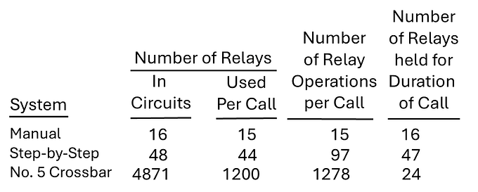
Table 1 – Comparative Use of Relays for an Inter-Office Call [7]
This table clearly shows the increasing complexity and reliance on relays in more advanced automatic switching systems like the Number 5 Crossbar, where many relays had very high usage but were held for only short intervals (~.4 seconds per invocation), freeing them for other new calls. Evidently 1200 relays were used to establish a local call on a Number 5 Crossbar exchange but only 24 were needed to maintain the same call during its duration. Very efficient use of resources.
Finally, you will enjoy this video produced by the Bell System on the design and manufacturing of the Wire Spring relay. At time stamp 20:15 there is reliability discussion of testing relays to withstand one billion operations. The opening sequence is a parade of ~40 relays dancing.
Conclusion
Ultimately, the commitment to improving relay contact reliability (enhanced call quality) was not just an engineering triumph but an economic necessity. It reduced manufacturing costs, operational power consumption, and, critically, maintenance expenses by ensuring longer-lived and more dependable switching systems.
Starting in 1965 transistor-based electronic switching caused a gradual reduction in the number of relays in use. Nevertheless, the electromechanical relay remains a testament to the ingenuity of telephone systems engineering and serves as an enduring tribute to the Bell System's, and other international companies, commitment to excellence. See [25] for more on vintage relay-based telephone systems.
See Appendix B for some thoughtful comments by experienced Switchmen on maintaining Step-by-Step and Crossbar equipment.
Appendix A
The Complex Transients of Relay Contact Interactions
From a distance, a relay’s opening (or closing) contacts may seem very simple. At a high level, it’s a Boolean zero/one operation. However, if we zoom into the first few milliseconds when contact separation (or arrival) begins a complex dance become apparent.

Fig A1, Relay contact (a) bounce, (b) chatter, and test circuit [from 22]
Figure A1 shows contact bounce and chatter in a circuit powered by 48vdc. The time scale is typically ~0-5 milliseconds but depends on the relay type. Some authors define bounce as a type of chatter or even the same as. Regardless, the figure shows different styles of signal interruption when contacts open or close. The interconnect wire is a transmission line with inductance and capacitance and is responsible for many aspects of the transient voltage’s characteristics as will be seen.
Fig A2 shows the voltage waveform of opening (unprotected) relay contacts as in the Fig A1 circuit. The bounce/chatter are partially responsible for this waveform’s look. This is a synthetic image showing the different modes that may occur during contact opening. It is not meant to imply that all opening transients display this exact form.

Fig A2 voltage waveform at opening of unprotected contacts [22].
The number of sparks and arcs at each opening may run into the hundreds, and current and voltage may momentarily reach peaks of 10 amperes or 2,000 volts. High frequency (HF) oscillations may be set-up, involving the connecting wire’s characteristics and stray capacitances [2, 22].
The figure notes, “glow discharge”. What is this? Glow discharge is a plasma formed by the passage of electric current through a gas. For air at room temperature and pressure, a ~300V contact potential is required at a gap of ~0.0001 inch (~2.5 um) to initiate a visible glow [24, Fig 9.12]. This phenomenon is also responsible for the light given off by neon tubes and fluorescent lamps.
Fig A3 shows a transient for an opening contact under load (no protection). The contact chatter is obvious.

Fig A3, transient response of a contact opening under load [2]
Conclusion
The simple relay is not so simple after all. The physics involved in contact interaction is very complex and took engineers and physicists many years to get a grip on the transient dynamics. While both closing and opening operations involve transient voltages and currents that can cause erosion, the high voltage transients and repetitive arcing during contact opening are far more energetic and destructive, leading to most of the contact wear.
Over time, these insights assisted relay designers to improve the contact metals, reduce closing/opening contact erosion and advance protection networks all leading to greater reliability. The next time someone refers to a simple relay, think again.
Appendix B
Comments on Exchange Maintenance by Experienced Switchmen
The Facebook Group Telephone Switching has some members that previously worked as repair technicians (Switchmen) inside Step-by-Step, #5 or #4 (toll) Crossbar exchanges. I kindly asked several of these experts (June 2025) to share some of their troubleshooting experiences. The comments below are edited for brevity.
Remember that relay reliability improved steadily from the early 1900s until the 1960’s. Naturally, the comments reflected on repairing faults in the 60s and 70s (much better reliability) not the 30s and 40s (much worse reliability). Here are some comments in no particular order:
I worked for several years in the Number 5 Crossbar and #4 Crossbar tandem offices. We only had a few "flat spring" relays, and I don't recall an abnormal amount of contact burnishing on the ones that we had. I recall a lot of contact contamination was from covers being loose on wire spring relays caused by vibration. -- Leonard Cowart
I worked in the Berkeley California number five Crossbar in the early 60s and burnishing the contacts was only necessary when there was a fault, but this was not common. The biggest routine we had was cleaning the machine of dust (with a vacuum). -- Dennis Alexander
Wire clippings falling on the Crossbar switch’s “banjo wiring” was our biggest problem. -- Craig Hille
Burnishing wire spring relay contracts was only done after pinpointing the fault location by tracing the failure using circuit diagrams and trouble card references. Other trouble reports were solder splashes on jumper frames, flipped contacts on a relay, a crooked cover, improper tension on relay springs, failed relay windings and blown fuses. -- Smitty Lancaster
I worked as a switchman in a SxS office. I would burnish relay contacts daily. From time to time, new contacts would need to be welded onto the wire spring. --Robert Kulakowski
I was a number #5 Crossbar switchman in central New Jersey. The wire spring based central offices had far fewer dirty contact problems than in flat spring relay offices. The switch itself was very well designed and most of the troubles were man-made. The most common would be wire clippings falling onto relays and backside wiring. -- Ernie Maso
Our motto was, “When in doubt, spray it out” (compressed air or trichloroethylene). Over time contacts built up a residue of junk and troubles got even more difficult to trouble shoot! Vacuuming equipment frames became a lost art. --John Earley
The dial tone and completing markers were very reliable, except for the polar relays. They were the weakest link. -- Norm Smith
I worked on the #5 Xbar and #4 Xbar Tandem exchanges for ~14 years in Concord California. Very few wire spring troubles. Some equipment had flat spring relay “latching” issues. Those generally needed burnishing. Occasionally wire springs needed to be adjusted. --Leon Sullivan
I worked in Step-by-Step and Crossbar offices. For Step, it was the A relay (responds to dial pulses) that caught the brunt of the burnisher. In Xbar the “MS” (Marker Start) relays took a beating. Lots of times contact erosion was because of missing 185A/186A contact protection networks. --Jay Cathell
Burnished many LXP & LXP1 Marker relays in a #5 Crossbar office. (i.e., The LXP relay was involved with decreasing the operate time of a crossbar switch hold magnet by a factor of 3 using the equivalent of 178 VDC to speed up closure time [Ref 20].) Also, "stock" trouble was the 1&2 top (contacts) of the L (Line) relay-- John Kelly
I worked in a #5 Crossbar office in Huntington Long Island with two Marker groups, some with flat spring contacts and some with wire spring relays. Did not burnish too often but did adjustments mostly of the flat spring contacts. --Tom Chichester
One of the worst problems were the wire spring relays in a #5 Xbar office installed in the mid-70s. At that time Western Electric started making the wire spring relays with plastic spool heads instead of fiber. They were a nightmare because the spool head would crack and become loose and rotate on the armature. Their fix was just as much of a nightmare. They came out with little clamps to put on the cracked spool head. -- David Favre
Burnished many contacts on SxS switches. I maintained a 40-year-old 701 PBX in a VA hospital. I was the only one in the group that knew anything about it. --Ray Bader
Best way to keep contacts clean was a super clean switch-room. --Rolland Kling
OH! How i miss this, after 24 years, I could hear a bad switch struggling. -- William EX
Best switch man/switch technician I knew was Jim Flash Herndon in The GNBONCEUO3T office. He could pull a card from the trouble recorder analyze it for 5 or 10 minutes and tell you what relay and which contacts were most likely the problem. -- Billy Garner
I worked in SxS, #1 and #5 Crossbar. #5 was by far my favorite. --Joseph Ruscigno
References